310 V DC High-Voltage BLDC Fan Motor: Design and Selection Guide
A 310 V DC bus removes the low-voltage supply from the blower design, but it changes stack-height selection, control wiring and creepage. What to fix before the first prototype.
On this page
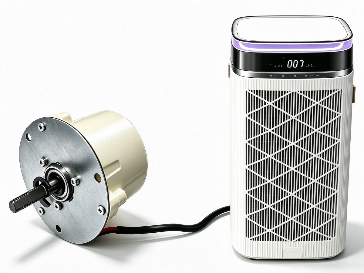
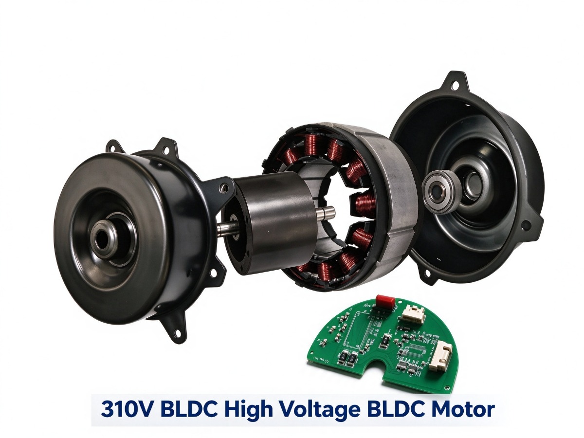
A 310 V DC BLDC fan motor runs from the rectified and filtered mains bus that many HVAC platforms already produce. In the ReputeCo 94 mm stator platform it is a three-phase, 200 W motor with 20–35 mm lamination height, an ø8 shaft and an interior-rotor layout, supplied alone or as a set with an HL9435 driver board. This guide covers the voltage, the stack height and the control interface.
What 310 V DC means at the terminals
310 V DC is not a battery voltage. It is what a 220–240 V AC supply becomes after rectification and smoothing: 230 V RMS times the square root of two gives about 325 V, and the bus sags to roughly 310 V under load. The motor therefore sees a high-voltage rail that is live whenever the equipment is plugged in, and that drives insulation, creepage and connector choice more than the control scheme.
Two consequences follow. The motor is not a 24 V or 48 V device and must never run from a low-voltage supply. And because the bus is always live, wiring, connectors and service procedures must assume mains-level hazard even though the label says DC.
Why the design skips the low-voltage PSU
Most 24 V BLDC blowers need a separate AC-to-24 V supply, which costs money, takes volume and adds a failure point. A 310 V motor takes the bus directly, so the only conversion left is the inverter stage. On a range hood or a commercial centrifugal blower that removes one box from the build.
- One conversion stage instead of two, so losses concentrate in the inverter.
- No external PSU to source, mount, certify or hold as a second part number.
- Lower current for the same power: a 200 W load draws under 1 A at 310 V.
- Motor and board matched as a set, fixing gate drive, current sense and protection in one design.
Stack height: 20–35 mm maps to torque and static pressure
Stator outer diameter is fixed at 94 mm, so lamination height is the main lever. More stack means more iron and copper in the same footprint, which raises torque per amp and holds speed against higher static pressure. Less stack means lower iron loss, lower cost and quieter low-airflow running. The BLDC motor range lists the platforms; 200 W is the ceiling for this stator, so the load calculation comes first.
| Lamination height | Air performance | Typical equipment |
|---|---|---|
| 20–22 mm | Low to medium air volume, lowest noise | Bathroom and ceiling exhaust fans, quiet purifiers |
| 25 mm | Medium volume, moderate static pressure | Air purifiers with combined HEPA and carbon stages |
| 30 mm | High static pressure, long duct runs | Centrifugal blowers, ducted ventilation, air curtains |
| 35 mm | Highest pressure in the platform, near 200 W | Range hoods, heavy filter banks, compact blowers |
Two rules keep the choice honest. Check the duty point at the highest expected pressure, because a blower sized at free air will not hold speed once a filter loads. And keep continuous load inside 200 W with margin; running at the ceiling shortens capacitor and board life. The BLDC versus AC comparison applies the same logic at lower power.
PWM, VSP and the HL9435 driver board
Standard control is a PWM input: cheap, isolated at the driver input and easy for a main controller to generate. VSP, a 0–10 V analog signal, is the option when the equipment already uses analog setpoints, when the harness runs long, or when the control board cannot produce a clean PWM at the required frequency. Both command the same inverter; the difference is noise immunity and wire count.
The HL9435 board is matched to this motor and supplied as a set. A third-party driver is possible, but gate drive, current limit and thermal protection then have to be re-validated against this stator, and creepage must suit a 310 V bus rather than a 24 V one. A matched set closes that loop and fixes responsibility for the combined thermal test.
Five integration mistakes
- Connecting the motor to a 24 V or 48 V supply and expecting rated torque.
- Sizing stack height at free air, then finding the blower loses speed on a loaded filter.
- Routing the PWM harness beside switching wiring without shielding, which shows as jitter.
- Mounting the driver where it sees airstream heat, so it derates silently.
- Skipping dielectric and creepage checks because the label says DC.
The 310 V platform is a system decision: stack height from the duty point, then driver and control interface as one matched set.
Frequently asked questions
Can I run a 310 V BLDC motor from a 24 V supply?
No. The winding and driver are designed for a high-voltage bus, and 24 V cannot produce rated speed or torque. For a low-voltage platform, use a 24 V motor from the same range rather than adding a boost stage.
Is VSP better than PWM?
Neither is better in general. PWM is simpler to generate and needs fewer wires. VSP tolerates long harness runs and electrical noise. Choose by what the main controller outputs and how far the signal must travel.
How do I know the stack height is right?
Measure airflow and static pressure at the worst filter or duct condition, then check the motor holds target speed with load inside 200 W. The BLDC-HV310 page lists the four standard heights; contact us with your blower curve.
Need a motor matched to your appliance?
Send your voltage, speed, shaft and mounting requirements. Our engineering team replies with a proposal, drawing and sample plan.
Request a quote