Custom BLDC Motor Development: From Spec Sheet to Mass Production
Custom BLDC projects fail on missing inputs more often than on design. What to send, the six development stages, the validation tests and the documents to expect.
On this page
A custom BLDC motor project fails more often from a missing input than from a design mistake. The supplier can size magnets, windings and a board, but only the equipment maker knows the duty point, the ambient and the space. This article sets out what to send, the six stages a project passes through, and the tests and documents that should exist before the first volume order.
What to send us before design starts
Before a design engineer can choose a stator, three numbers have to be fixed: airflow and static pressure at the worst operating condition, the ambient temperature at the motor, and the supply available inside the chassis. Stack height, winding, bearing type and whether the driver sits on the motor or in the appliance all follow from those three.
- Duty point: airflow, static pressure and the impeller or blower drawing.
- Supply: single-phase 110 or 230 V, a DC rail and its tolerance, or a 310 V bus.
- Environment: ambient range, humidity, dust or oil, and mounting orientation.
- Mechanical envelope: shaft diameter and length, flange or bracket, length limit.
- Control: PWM, 0–10 V, tachometer output, closed loop, and connector type.
- Compliance and volume: certifications required, annual quantity and ramp plan.
The six-stage development path
The stages are sequential, but the review gates are where a project is actually controlled. Each gate should produce a document both sides sign, because a change after the prototype stage costs far more than a change at the spec review. A project that skips the pilot run usually discovers its yield problem in the first customer shipment.
| Stage | Main inputs | Output |
|---|---|---|
| 1. Spec review | Duty point, supply, envelope, compliance | Frozen requirement list and open questions |
| 2. Design and DFM | Frozen spec, target cost, volume | Magnetic and winding design, drawings, board layout |
| 3. Prototype | Released drawings, tooling plan | Samples with measured performance curves |
| 4. Validation | Samples, test plan, limits | Performance, temperature rise, dielectric, noise, RoHS records |
| 5. Pilot run | Approved design, process sheets | Small batch on production tooling with yield data |
| 6. Mass production | Signed pilot report, purchase order | Scheduled output against 300,000 pcs/month capacity |
Validation, and the documents that go with it
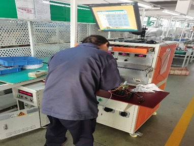
Validation is where a motor stops being a sample. Performance is measured on a test bench against the duty point. Temperature rise is measured in the application or in a chamber at the declared ambient. Dielectric strength and insulation resistance are checked on every unit or by sample, depending on the safety class. Noise and vibration are checked at the mounting arrangement the appliance uses.
- Performance test: speed, torque, current and input power across the load range.
- Temperature rise: winding and bearing temperature at declared ambient, at rated duty.
- Dielectric strength and insulation resistance at the class-appropriate test voltage.
- Noise and vibration: sound pressure at a defined distance, plus a tone check across speed.
- RoHS verification by XRF on incoming materials, with material declarations on file.
The documentation package for a validated motor includes the dimensional drawing with tolerances, the winding and electrical specification, the performance curve, the test report, the material and RoHS declarations, and the handling and mounting notes. For a regulated appliance, the compliance statements and certificate copies belong in the same package.
Pilot run to mass production
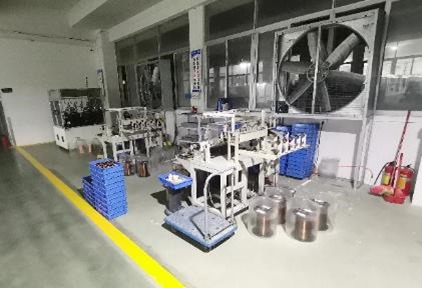
A pilot run uses production tooling and production process sheets, not prototype tooling, which is the only way to see the real yield. It also confirms fixtures, packing and traceability, and only when the pilot report is signed should volume be released. The factory runs five assembly lines, ten winding machines and a varnish shop, with ISO 9001:2015 certification and a capacity of 300,000 pieces per month, as set out on the company page; the motor range shows where a project can start, and contact opens a spec review.
A custom motor is a document trail as much as a design: freeze the spec, gate every stage, and the volume order becomes a formality.
Frequently asked questions
How long does a custom motor project take?
It depends on how much is new. A winding or shaft change on an existing platform is fast; a new stator, a new board and a pilot run is a multi-month project. Tooling and how quickly samples can be tested in your appliance drive the schedule.
Can you work from a sample instead of a drawing?
A sample is a useful starting point, especially for mechanical fit, but it cannot replace the duty point and the ambient. Reverse-engineering a sample without those numbers usually produces a motor that fits and underperforms. The 310 V DC guide shows how much a duty point changes a selection.
Who owns the tooling and the drawings?
Agree it in writing at quotation stage, not at the end. Ask explicitly, together with the change-control procedure, so a later component substitution cannot alter the motor without your approval. Start from the BLDC-RH8218 platform if you want to see the documentation depth available.
Need a motor matched to your appliance?
Send your voltage, speed, shaft and mounting requirements. Our engineering team replies with a proposal, drawing and sample plan.
Request a quote