Air Purifier Motor Selection: Static Pressure, PWM Control and 30 dB Noise Targets
Air purifier motors are sized by the pressure at end of filter life, not by clean-filter airflow. A guide to the pressure budget, closed-loop control and a 30 dB target.
On this page
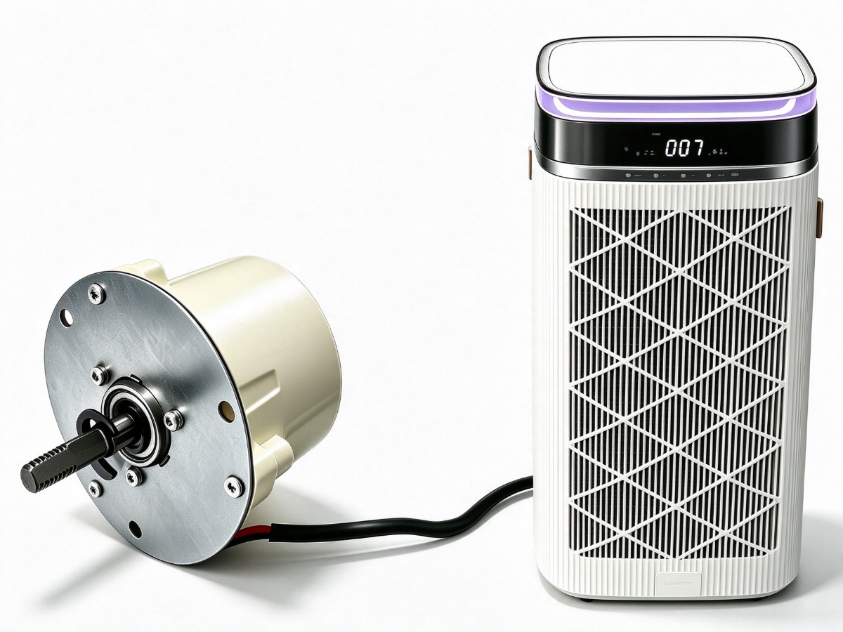
An air purifier motor is chosen by the pressure it must overcome at the end of the filter life, not by the airflow printed on a clean-filter datasheet. As a HEPA stage loads, its resistance rises and a fixed-speed fan delivers less air, exactly when the room needs more. This guide covers the pressure budget, closed-loop airflow control, PWM compatibility and how to hold a 30 dB target.
Filter pressure drop is the real design load
Every stage in the air path adds resistance, and the total is what the impeller works against. A pre-filter costs little pressure; a HEPA stage dominates and rises as it captures dust; carbon adds a steady but smaller drop. Motor and impeller must be selected against the loaded total, or clean-air delivery falls below the claim without anyone noticing.
| Filter stage | Pressure drop, clean | Pressure drop, loaded |
|---|---|---|
| Coarse pre-filter | 10–30 Pa | 40–80 Pa |
| HEPA H13 | 150–250 Pa | 300–450 Pa |
| Activated carbon | 30–60 Pa | 80–120 Pa |
| Pre-filter plus HEPA | 160–280 Pa | 340–530 Pa |
| Full stack with carbon | 190–340 Pa | 420–650 Pa |
Those ranges are typical of residential purifiers at rated airflow, and they show the shape of the problem: the loaded stack can need nearly twice the pressure of the clean one. Use the filter supplier curve for the real design, then add housing, grille and duct losses on top.
Why constant airflow needs closed-loop control
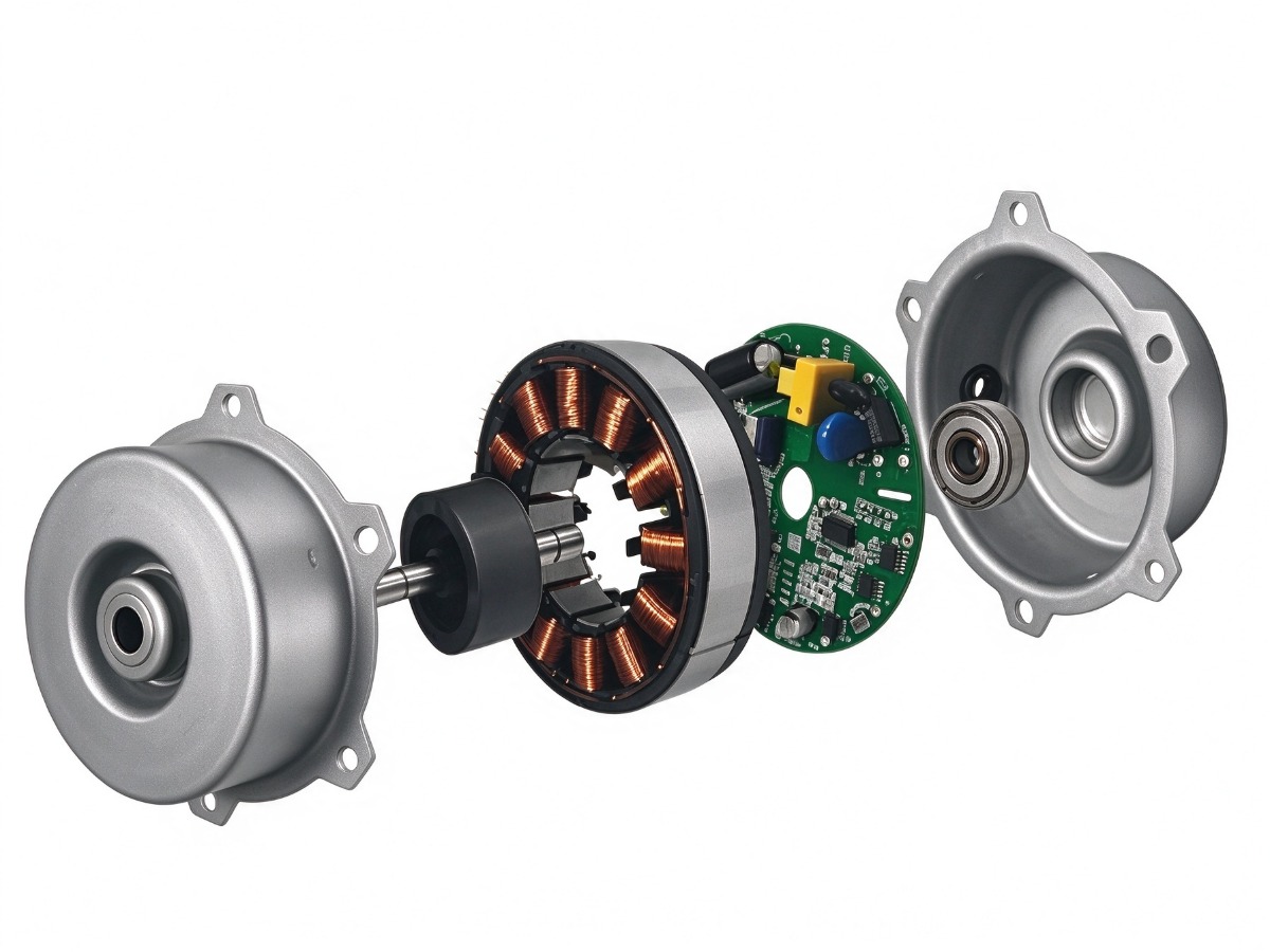
A fixed-speed fan on a rising pressure curve delivers falling airflow. The usual fix is to run the motor faster as the filter loads, which needs speed feedback rather than a fixed PWM duty. The BLDC-RH8218 carries closed-loop speed control on the board with a 5 V analog input and a PWM input, so the controller holds a target speed against changing pressure without an external sensor.
- Airflow stays close to target as the HEPA stage loads, so clean-air delivery holds.
- Speed no longer drifts with line voltage or motor temperature.
- Fan behaviour is predictable: pressure rises with the square of speed, power with the cube.
- Fewer field complaints about a unit that seems to weaken over months.
Closed loop is not the same as constant airflow. Holding speed constant still loses a little airflow as pressure rises, because the impeller curve is not vertical. If the claim depends on true constant airflow, the controller needs an airflow or pressure signal, and the motor needs a command fast enough to follow it.
PWM compatibility and a 30 dB target
PWM input on these motors is a logic-level signal, and the two numbers that cause trouble are frequency and threshold. The BLDC-RH4214 accepts 10–60 kHz with 5 V high and 0.4 V low; a controller with 3.3 V logic may sit too close to the high threshold, which shows up as a fan that starts only sometimes. Check input thresholds, not just the nominal voltage.
Noise behaves the same way. A motor such as the BLDC-RH4214 is rated at or below 30 dB(A) with a 30,000 h design life, and that figure comes from a bench. In the appliance the impeller, filter frame and panels add their own contribution, and a small resonance at one speed can dominate. Isolate the motor with rubber grommets, avoid mounting it on a large flat panel, and sweep the speed range for tones instead of testing one point. The motor range lists the purifier options, and contact covers samples.
What to request from a supplier
- A performance curve at the loaded pressure, not only at free air.
- The PWM or analog input specification: thresholds, frequency range, pull-up requirements.
- Noise data at the mounting arrangement, with the measurement distance stated.
- Life and protection data: bearing type, design life, locked-rotor and reverse-polarity behaviour.
- Insulation and ingress: class, IP rating, and whether the board is conformally coated.
- Change control: what happens to the magnetic design or board if a part is substituted.
Size the motor against the loaded filter, then close the loop, so the loss as the filter fills never becomes a customer complaint.
Frequently asked questions
How much airflow loss is acceptable as a filter loads?
It depends on the claim and the filter. A fixed-speed fan can lose a large share of its clean airflow by end of life; a closed-loop unit holds speed and loses less. Decide the end-of-life airflow first, then pick the control scheme that can deliver it. The dehumidifier motor guide applies the same duty thinking to a wetter air path.
Can one motor cover several purifier models?
Sometimes. The RH8218 covers a 48 W duty, and the RH7816 induction motor spans 30 W to 45 W in the same frame, so a platform can scale by rating. Check the impeller and pressure budget for each model before assuming one motor fits the family.
Does a higher speed always mean more noise?
Not linearly. Aerodynamic noise rises steeply with tip speed, and above a point the impeller becomes the dominant source rather than the motor. If the target is 30 dB(A), the answer is usually a larger impeller at lower speed, not a faster motor.
Need a motor matched to your appliance?
Send your voltage, speed, shaft and mounting requirements. Our engineering team replies with a proposal, drawing and sample plan.
Request a quote