PWM vs 0–10 V (VSP) Speed Control for Fan Motors: Wiring and Compatibility
A PWM input reads duty cycle and a VSP input reads voltage, and swapping them makes a fan run flat out or hunt. Here is how each signal behaves and what to check before sign-off.

On this page
A BLDC fan motor usually exposes one speed-control input, and the two common forms are a PWM logic signal and a 0–10 V analog voltage. They are not interchangeable: a PWM input measures duty cycle, while a VSP input measures a steady DC level. Wiring the wrong one gives a fan that runs at full speed, hunts, or refuses to start. On the BLDC-RH4214 the input is PWM only; on the 310 V platform PWM is standard and VSP is an option.
How a PWM speed input works
The controller measures duty cycle, not voltage. A 5 V level reads as high and 0.4 V or below as low, so the input works with 5 V logic and with open-collector drivers that pull the line down. The carrier must stay inside 10–60 kHz: below that band the motor can audibly follow the pulses, above it the input filter rounds the edges until the duty reading drifts. Speed then follows duty, from minimum to full at 100 %.
- Logic high 5 V, logic low 0.4 V, so a 3.3 V driver needs a level shift.
- Carrier 10–60 kHz, above the audible band and inside the input filter.
- Duty cycle sets the speed request; closed-loop variants keep speed feedback on board.
- An open input often means full speed on fan-profile firmware, not stop.
- Signal return goes to controller ground, not to the motor chassis.
How a 0–10 V (VSP) input works
A VSP input reads an analog voltage between 0 and 10 V and scales it to a speed setpoint. It is the language of building controllers, wall rheostats and older appliance boards, which is why it persists. On the 310 V platform the BLDC-HV310 takes PWM as standard and VSP as an option, with the input on the HL9435 driver board. The source must be able to hold its level while supplying the input bias current, or the speed will sag at the top of the range.
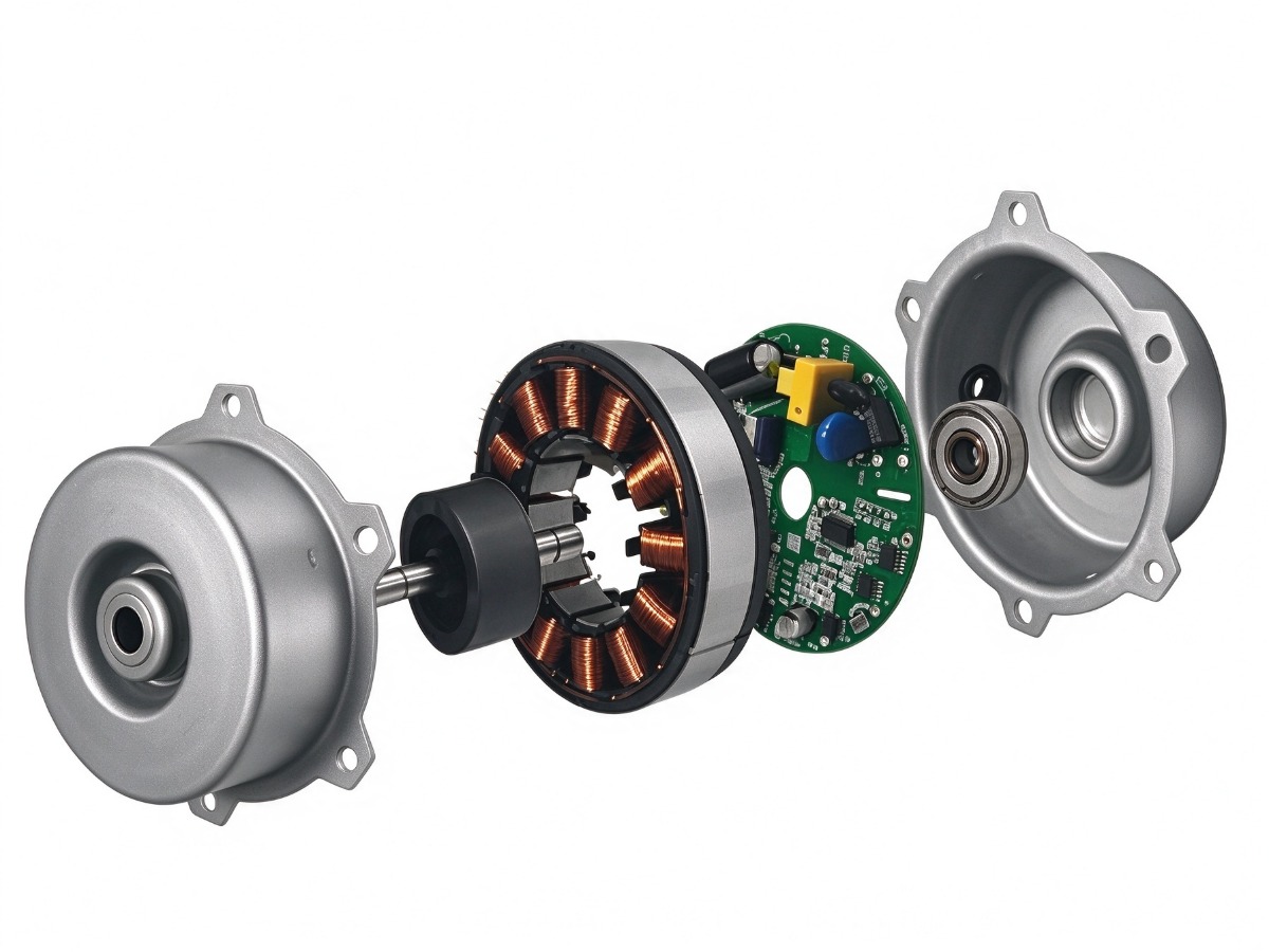
Mixing the two is the usual failure. A 0–10 V source driving a PWM input holds the line high, so the motor runs flat out. A PWM source driving a VSP input averages to a voltage that depends on duty and on the filter, so speed becomes unpredictable and slow to settle. Where an appliance must support both, specify a motor with dual inputs, such as the BLDC-RH8218, which accepts a 5 V analog signal and PWM and closes the loop on built-in speed feedback. The architecture comparison explains where that board sits.
Signal comparison
| Parameter | PWM input | 0–10 V (VSP) input |
|---|---|---|
| Signal type | Square wave, duty encoded | Steady DC level, amplitude encoded |
| Levels | 5 V high, 0.4 V low | 0–10 V over the full speed range |
| Frequency | 10–60 kHz carrier | Not applicable, DC |
| Source | MCU pin, open collector, 5 V logic | Controller analog output or potentiometer |
| Noise | Insensitive to drift, sensitive to edge quality | Sensitive to ground offset and induced noise |
| Cable run | Short runs inside the appliance | Longer runs with shielded cable |
| Typical fit | Appliance board with a spare timer output | Building controller, wall control, retrofit |
Ground reference, level shifting and cable length
Both signals are single-ended, so the return path is part of the circuit. A 3.3 V microcontroller driving a 5 V PWM input sits below the specified high threshold, and the duty reading becomes jittery at low duty. One small-signal transistor or a level-shift IC fixes it. Keep the signal return away from mains earth and from the motor power ground, so switching current does not lift the reference. Beyond about a metre, use shielded cable bonded at the controller end only.
- Bond signal ground to controller ground at one point.
- Shift 3.3 V logic to a clean 5 V swing.
- Twist signal and return, and keep them off mains.
- Above one metre, shield the run and bond one end.
A speed signal is a measurement, not a switch: define the levels, the return path and the failure state before the harness is drawn.
Commissioning checklist
- Confirm the motor variant: PWM only, VSP only, or dual input.
- Measure signal high and low at the motor connector while the fan runs.
- Check the carrier frequency sits inside 10–60 kHz on a scope.
- Sweep duty from 0 to 100 % and log speed at five points.
- Verify minimum speed and stop behaviour match the appliance spec.
- Disconnect the signal and confirm the motor does what the spec says.
- Repeat the sweep on the final harness length at both supply extremes.
Frequently asked questions
Can a 3.3 V microcontroller drive a 5 V PWM input?
Not reliably. The input needs 5 V to register a clean high, and a 3.3 V swing sits in the undefined band, so the duty reading jitters at low duty. Add a level shifter or a small NPN stage that pulls the line to 0 V.
Why does the fan run at full speed with no signal connected?
Many fan profiles treat a missing signal as a request for full cooling rather than a fault, which is the safe direction for a cooling fan. If the appliance needs fail-stop instead, state that as a firmware requirement at sample stage.
Which input suits a multi-fan installation?
0–10 V distributes more easily across several fans: each unit draws only a bias current and one pair of wires can feed the rack. PWM also works if the controller can drive several inputs in parallel, but the input filters then load the shared driver, so check the aggregate load. Standard ratings are on the product pages.
Need a motor matched to your appliance?
Send your voltage, speed, shaft and mounting requirements. Our engineering team replies with a proposal, drawing and sample plan.
Request a quote