Integrated or External Driver? BLDC Motor Architecture for Appliance OEMs
One mains connection and no driver board, or a split motor and driver set? A practical comparison of the two BLDC architectures at the points that decide the design.
On this page
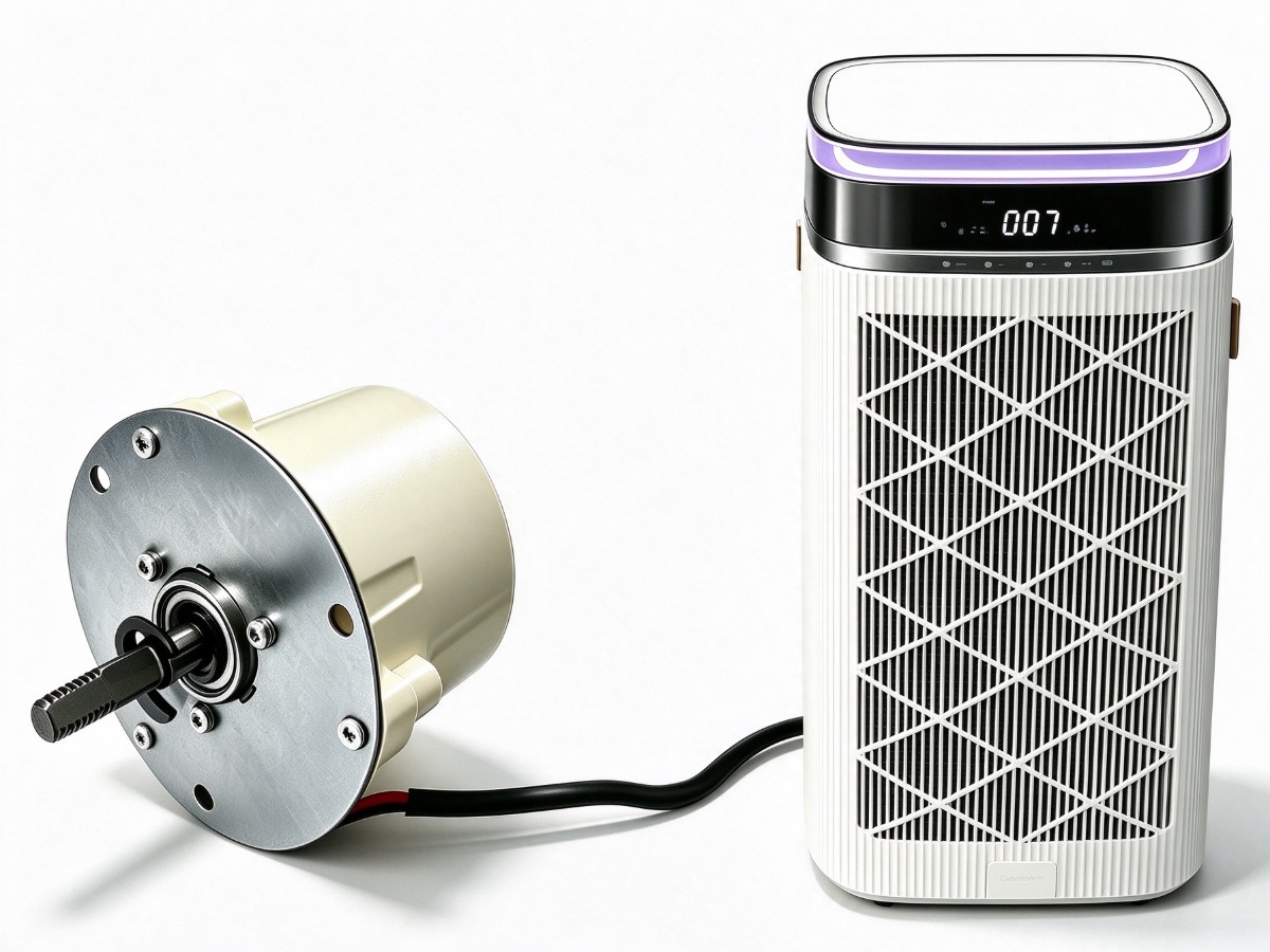
An integrated BLDC motor carries its power supply and control electronics inside the motor housing, so the appliance connects mains AC directly to the motor leads. An external-driver architecture splits those functions: motor on the bracket, driver board mounted elsewhere and wired to it. The choice changes part count, assembly time, wiring, thermal design and the spare-part list, so it belongs in the mechanical review rather than the electrical BOM. The BLDC-RH7612 is a typical integrated unit at 24 W.
What an integrated driver actually contains
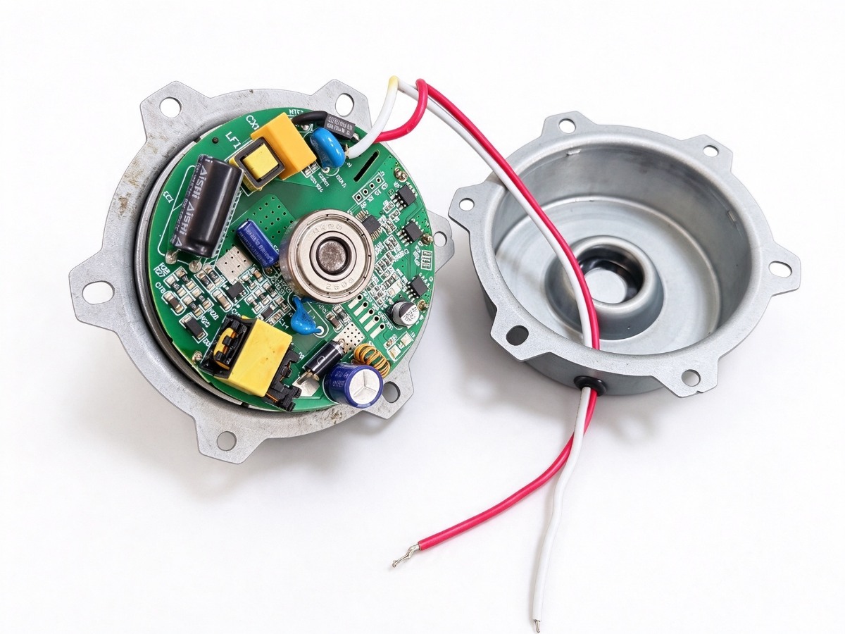
The driver here is not a small add-on board. The BLDC-RH7612 takes AC 200–240 V, 50/60 Hz directly and converts it to an internal 24 Vdc rail on a built-in switch-mode power board, then drives a three-phase winding from a stacked control board. Output is 24 W at 1500 rpm, ø8 shaft, IP54, class F. The smaller BLDC-R-MD8E follows the same pattern at 6 W with an internal 12 V rail and 2100 rpm.
- Switch-mode AC-to-DC power stage with mains filtering on the same PCB
- Three-phase inverter and commutation logic on a second board
- Speed input on the control board, taken out through the housing lead exit
- Terminal block for mains and speed signal
How the external 310 V architecture is built
The alternative puts the electronics in their own enclosure. The BLDC-HV310 is a three-phase 310 Vdc motor on a 94 mm stator, rated 200 W, with a 20–35 mm stack, ø8 shaft and interior-rotor construction. It is supplied with the HL9435 driver board as a motor-plus-driver set. PWM control is standard and a 0–10 V VSP input is optional. It cannot run from a 24 V or 48 V supply; the DC bus is produced by the driver.
Splitting the electronics away frees space and lets the board sit where the air is coolest, but it adds a harness, a second mounting point and a second stocked item. On a large centrifugal blower that is often worth it; on a small exhaust fan it rarely is.
Eight points that decide the choice
| Decision point | Integrated vs external |
|---|---|
| Part count | One motor part number replaces motor, driver board, DC harness and bracket; the split route stocks four items. |
| Assembly | Two mains leads and one signal lead; the split route adds driver mounting, DC bus wiring and a board test. |
| Wiring | Mains and speed wire inside the fan housing; the split route carries a switched DC cable between enclosures. |
| Space | Board sits inside the motor envelope; the bracket stays clear but the motor body is longer. |
| Thermal path | Power stage shares the winding airflow; an external board sits in the cool inlet zone on its own heatsink. |
| EMI | Short switching loops inside a metal housing; the split route adds a DC cable that can radiate. |
| Service | Field replacement means swapping the whole motor; board-level repair is impractical on a sealed unit. |
| Spares | One SKU covers motor and electronics; the split route keeps two SKUs and a matched pair. |
Thermal and EMI trade-offs
Both layouts work; they fail differently. In an integrated motor the power board shares the thermal path with the winding, so switching devices and copper heat the same air. At 6 W and 24 W the housing surface is enough of a heatsink, but the coupling caps how much power fits a small frame. Moving the board out gives it cooler air and a dedicated heatsink, at the cost of a DC cable carrying fast switching current.
Put the electronics inside the motor when the appliance has one fixed airflow and one mains connection; split them when the blower is large and the board needs its own thermal and service boundary.
Serviceability and the spare-part list
Field service is where they diverge most. A sealed integrated motor is replaced as a unit: unplug, unscrew, refit. The split architecture lets a driver be swapped alone, but only when the replacement matches the motor variant and the service partner stocks both parts. For OEMs selling into markets with long warranty chains, that shows up in the spares budget. Lead lengths, connectors and flanges can be customised either way; start with the engineering enquiry.
- Fixed airflow and a single mains connection: integrated.
- Above roughly 100 W with a large impeller: split, driver in the cool inlet zone.
- No in-house DC bus design resource: integrated.
- One board driving two identical blowers: split.
- Service network swaps complete assemblies: integrated.
Frequently asked questions
Is an integrated motor less efficient than a separate driver?
Not inherently. The power stage sits closer to the winding, so the copper run between board and motor is shorter. Efficiency differences come from the converter design and switching scheme, not from board location. Compare input power at the same operating point instead of assuming one layout wins.
Can one external driver run two motors?
Yes, if the driver is rated for the total current and the two motors are identical. Sharing one board across two blowers is the usual reason to keep the electronics outside the motor. Motor and driver still have to be specified as a matched set, which is how the HL9435 is supplied with the 310 V platform.
What should an OEM ask for in a sample?
Ask for motor and driver as a set, with the intended speed signal, cable length and connector. Request input power, speed and noise at the target operating point. The product pages list the standard ratings, and the speed control guide covers the signal side.
Need a motor matched to your appliance?
Send your voltage, speed, shaft and mounting requirements. Our engineering team replies with a proposal, drawing and sample plan.
Request a quote